PromoNetworkNotes
← Focused guides · Main promo index · Answering toolkit
38 checklist answers for topics 08–11. Each numbered subheading reproduces one revision-checklist item, with the explanation immediately below it. Main sources are the five school Network Slides PDFs. PDF references use the file’s page number (counting the first page as 1).
How to revise
Read a heading, cover its answer and explain it aloud. For calculations, work the example on paper before checking. Use the source links to revisit a slide.
Checklist location and source choices
The checklist items are in the parent folder’s main topic notes 08–11.
Solutions/08.mdto11.mdcontain practice answers, so they are linked where relevant. The exact checklist wording is preserved, including the reference to hardware in Network1; gaps are filled from the existing notes and Resources, with supplementary sources identified. Slide errors are called out rather than repeated. Worked examples and Mermaid diagrams are revision explanations created for this note.
Source labels: “Slide source” identifies school coverage; “Supplementary reading” points to VJC/A notes for the stated topic. Original worked examples and extra technical clarifications are identified explicitly. VJC links use PDF viewer page numbers. A notes links open the relevant file; the bold section name tells you where to read because many of its section labels are plain text rather than linkable headings.
Jump to: 08 Foundations · 09 Layers · 10 Addressing · 11 Protocols
08 - Network foundations, hardware and architectures
Checklist: 08 Network foundations, hardware and architectures · Practice solutions.
08.1 Explain LAN, WAN, internetwork, Internet and intranet and distinguish their scopes.
A network connects two or more computers/devices so they can communicate and share resources. A stand-alone computer is not connected to a network.
| Term | Meaning and scope | Example |
|---|---|---|
| LAN (Local Area Network) | A network confined to a small geographical area, such as a building or site. | School computer laboratory or campus network. |
| WAN (Wide Area Network) | A network spread over a large geographical area, connecting sites and often multiple LANs. | A company’s Singapore and overseas offices connected together. |
| Internetwork | Two or more networks connected together. It need not be worldwide or publicly accessible. | Two departmental LANs connected by a router. |
| Internet | The global system of interconnected networks communicating using TCP/IP. | The infrastructure used to reach public websites worldwide. |
| Intranet | An organisation’s private network/service environment, restricted to authorised users and using Internet technologies. | A staff-only portal containing internal documents. |
Exam distinction: LAN/WAN describe geographical scope; intranet describes private organisational access. An intranet can span several sites. The Web is a service using the Internet, not the whole Internet.
Supplementary reading: A notes: Network 1 — read Network types; VJC PDF pp. 438–449: LAN, WAN, Internet and intranet.
Slide source: Network1 pp. 8-13.
08.2 Describe network benefits and costs in a stated organisational scenario.
Link each benefit or cost to the organisation in the question: feature → consequence → relevance.
| Point | Applied explanation for a school |
|---|---|
| File/resource sharing | Teachers place lesson files in a shared location so students can access the same material. |
| Hardware sharing | Many computers use one network printer, reducing the number of printers needed. |
| Communication | Email, chat and video calls support collaboration between departments or sites. |
| Roaming access | Users sign in from different networked computers and access their files. |
| Central maintenance and security | Administrators distribute updates and enforce permissions centrally, reducing repeated work on individual machines. |
| Different access levels | Students can read lesson files while only teachers can modify them; access to confidential records can be restricted. |
| Equipment and staffing costs | Switches, cabling, servers and skilled administration require money and ongoing maintenance. |
| Malware and unauthorised access | An insecure connected device may expose shared files or help malware spread to other machines. |
| Dependence on availability | Failure of a central file server or a required network link can prevent access to resources. |
Model answer: “A central file server lets staff apply access permissions to confidential student records in one place. However, the school must pay for server equipment and administration, and an unprotected server failure could make those records unavailable.”
Supplementary reading: A notes: Network 1 — read Network → Advantages / Disadvantages of using networks. The school scenario is an application of those points.
Slide source: Network1 pp. 9-10; Network5 pp. 10-12.
08.3 Identify sender, receiver, message, medium and protocol.
| Component | Meaning | Example: browser requests a webpage |
|---|---|---|
| Sender | Device sending the data. | The user’s laptop. |
| Receiver | Device intended to receive it. | The web server. |
| Message | Information being communicated. | The HTTP request for a page. |
| Medium | Physical path carrying the signals. | Wi-Fi radio, Ethernet copper or optical fibre along the route. |
| Protocol | Agreed rules governing data format and communication. | HTTP for the request/response, supported by lower-layer protocols. |
For the response, the server becomes the sender and the laptop becomes the receiver. A router forwarding the message is an intermediate node, not the final application recipient.
The slides’ four qualities of effective communication are delivery to the intended recipient, accuracy, timeliness, and low jitter (variation in packet arrival timing). For live audio, uneven arrival times can disturb smooth playback.
Supplementary reading: A notes: Network 1 — read Data communication → Components in data communications.
Slide source: Network1 pp. 4-6.
08.4 Compare client-server with peer-to-peer architecture and justify a choice.
| Dimension | Client-server | Peer-to-peer (P2P) |
|---|---|---|
| Roles | Clients initiate requests; servers provide services and respond. | Each peer can request and provide resources. |
| Control | Central management of accounts, permissions, data and backups. | Each peer manages its own resources; enforcing consistent policies is harder. |
| Cost | Dedicated server resources and skilled administration may be costly. | Simple sharing can avoid a dedicated server and reduce setup cost. |
| Availability | A single unreplicated server is a point of failure for its service. | One peer failing need not stop the whole network, but resources available only from it are lost. |
| Consistency | A central data source makes maintaining a current copy easier. | Distributed copies may become inconsistent without synchronisation. |
| Growth/performance | Add clients and increase server capacity; an overloaded server can become a bottleneck. | New peers can contribute capacity, but performance depends on peers being online and their resources. |
| Suitable example | School accounts, central files, databases, websites. | Direct file sharing among a small group; BitTorrent. |
Choose client-server for confidential school records: central authentication, permissions and backups support controlled access. State the cost and server-failure trade-off.
Choose P2P for a few users sharing non-critical files on a small budget: each can share resources without a dedicated server. State that availability and security depend on individual peers.
Architecture is about roles
P2P does not mean every computer has a physical cable to every other computer. A P2P service can run over a star-shaped LAN.
Supplementary reading: A notes: Network 4 — read Client-Server architecture and Peer-to-peer (P2P) architecture; VJC PDF pp. 468–470: architectures.
Slide source: Network5 pp. 8-15.
08.5 Explain roles of NIC, hub/repeater, switch, router and other devices taught in Network1.
1. How the physical devices are connected

You can read this diagram as:
Internet → Modem → Router → Switch / Hub → end device
Their roles are:
- Modem: Converts signals as required by the Internet access connection.
- Router: Connects different networks.
- Switch / Hub: Connects devices within the same LAN.
- Access Point: Allows wireless devices to join the LAN.
The diagram does not show:
- NIC: Located inside, or at the network interface of, each workstation, laptop, router, or other connected device.
- Repeater: Can be placed along an excessively long physical link to regenerate the signal.
- Hub: Essentially a multiport repeater.
This order is a typical example, not a compulsory arrangement. A home “router” often combines Router + Switch + Access Point, and sometimes Modem, inside one physical box. Image and explanation source: Baeldung
2. Why devices correspond to different layers
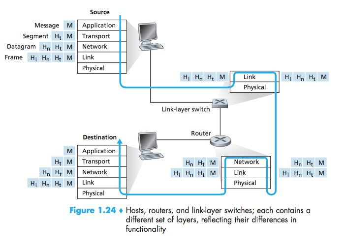
This diagram shows the distinction between a physical device and the layers it processes:
- A Host uses the complete protocol stack.
- A Link-layer switch mainly processes:
- Physical layer
- Link / Data Link layer
- A Router mainly processes:
- Physical layer
- Link / Data Link layer
- Network layer
It does not mean:
A switch is a physical object placed inside the Data Link layer.
It means:
A switch receives bits/signals at the Physical layer and examines frames and MAC addresses at the Data Link layer.
Similarly:
A router must also receive signals and frames, but it goes one step further and examines packets and IP addresses at the Network layer.
Putting the ideas together
Internet
   │
 Modem                signal conversion
   │
 Router               Network layer: IP address / packet
   │
 Switch or Hub        Data Link layer: MAC address / frame
   │                   Physical layer: bit / signal
 Access Point
   │
Laptop's NIC
The first picture shows how the devices are physically connected. The second shows which layers each device needs to process to perform its job.
Looking at both pictures together is less confusing than simply placing device names into an OSI model table.
Identify the function being performed, then name the device. The checklist wording mentions Network1, but that PDF does not explicitly teach every device in the table. Use these supplementary sources for the missing explanations:
Where to read the hardware explanations
- NIC: VJC PDF p. 440, §1.4: Computers with Network Interface Cards.
- Hub, switch and router: A notes: Network 2 — read Network devices, near the end of the file; also VJC PDF p. 441: Switches and Hubs; Routers. For routing-table detail, use VJC PDF pp. 457–459, §7.7: IP Packets, Routers and Routing.
- Modem: VJC PDF p. 441, item 5: Modem, for signal conversion.
- Wireless access / base station: VJC PDF pp. 441–442, §1.5: How is a WLAN created?. The table expresses that role as a separate access-point function.
- Repeater: A notes: Network 1 — read Physical topology → Ring Topology; it states that a repeater regenerates and passes on bits. The school also states this in Network1 p.37.
Read these for the named roles, not as an expansion of your teacher’s confirmed exam scope. VJC sometimes groups routing, DHCP and Wi-Fi in one consumer device; the table below separates those functions.
| Device | Core role | Typical layer / decision |
|---|---|---|
| NIC (Network Interface Card/controller) | Provides a host’s network interface; transmits/receives signals and supports link frames and MAC addressing. | Physical and data link. |
| Repeater | Regenerates received signals to extend a link’s reach. | Physical; no MAC/IP forwarding decision. |
| Hub | A multiport repeater: repeats incoming signals to the other ports. | Physical; no address table or selective forwarding. |
| Switch | Connects devices within a LAN and forwards frames using destination MAC addresses and a learned MAC-to-port table. | Data link for an ordinary Layer 2 switch. |
| Router | Connects different IP networks; consults a routing table to select an outgoing interface/next hop. | Network; destination IP address. |
| Wireless access point | Lets wireless clients join the LAN, commonly bridging wireless and wired links. | Primarily physical/data link. |
| Modem | Modulates/demodulates signals for the relevant access technology. | Signal conversion; does not by itself imply IP routing. |
A home “router” box may combine routing, switching, Wi-Fi access point, DHCP and sometimes modem functions. Describe the specific role requested. A repeater/hub cannot choose an IP route; an access point alone is not a substitute for a router between subnets.
Supplementary reading: A notes: Network 2 — read Network devices; VJC PDF pp. 440–442: LAN components and WLAN setup. See the device-by-device reading directions above.
Slide source: Network1 pp. 18-21; Network1 pp. 37; Network1 pp. 41-49; Network2 pp. 6-9.
08.6 Distinguish frame forwarding by MAC address from routing by IP address.
| Comparison | Switch forwarding | Router forwarding |
|---|---|---|
| Data unit | Ethernet frame. | IP packet. |
| Address inspected for forwarding | Destination MAC address. | Destination IP address. |
| Table used | MAC address → switch port. | Destination network/prefix → next hop or interface. |
| Main scope | Delivery within a LAN. | Delivery between IP networks. |
| Link frame | Forwards the frame within the link-layer network. | Removes the incoming frame and builds a new frame for the outgoing link. |
A switch learns where a device is by recording the source MAC address and incoming port. For a known destination it forwards to the associated port. Unknown-destination and broadcast frames may be flooded to other eligible ports; do not claim a switch always sends to exactly one port.
Example: A sends to B on another subnet. A’s Ethernet frame is addressed to the default gateway’s MAC, while the enclosed IP packet is addressed to B’s IP. The switch forwards towards the gateway; the router routes towards B.
Supplementary reading: A notes: Network 2 — read Network devices → Hub / Switch / Router; VJC PDF pp. 457–459: IP packets, routers and routing. These support the MAC-table versus routing-table distinction; the detailed switch-learning/flooding paragraph is an additional explanation.
Slide source: Network1 pp. 41-49; Network2 pp. 6-9.
08.7 Compare transmission media and simplex, half-duplex and full-duplex modes where taught.
| Medium | Signal / use | Strengths | Limits / choice |
|---|---|---|---|
| Twisted-pair copper | Electrical signals; common Ethernet LAN cabling. | Relatively inexpensive; twisting reduces crosstalk/interference. | Distance and electromagnetic interference constrain links; useful for ordinary short LAN runs. |
| Coaxial cable | Electrical signals through a central conductor with insulation and shielding. | Shielding reduces interference; used for cable TV/access and older networks. | Bulkier and less common for modern endpoint LAN cabling. |
| Optical fibre | Light pulses through glass/plastic fibres. | High capacity, long distances, immunity to electromagnetic interference. | Equipment/installation can cost more; suitable between buildings or in electrically noisy environments. |
| Radio waves | Wireless links such as Wi-Fi/mobile networks. | Mobility and fewer endpoint cables. | Shared capacity, interference, obstacles and coverage affect performance. |
| Microwaves | Wireless terrestrial or satellite links. | Can connect distant sites without laying a continuous cable. | Path/line-of-sight constraints; satellite paths can add substantial delay. |
| Infrared | Short-range light-based communication. | Useful for short-range directional links such as remotes. | Obstacles can block the signal; limited range. |
The slides identify these media; the selection trade-offs expand the existing revision note. Avoid choosing a medium solely because it is “fast”: link it to distance, required capacity, interference, mobility and budget.
| Mode | Direction | Example |
|---|---|---|
| Simplex | A → B only. | One-way broadcast; the slides’ simplified keyboard-to-computer example. |
| Half-duplex | A → B, then B → A; both directions, one at a time. | Walkie-talkies. |
| Full-duplex | A ⇄ B; both directions simultaneously. | Telephone conversation / full-duplex switched Ethernet link. |
Physical topology recall: mesh has links between every pair in a full mesh; star connects endpoints to a central device; bus shares a backbone; ring connects each device to two neighbours. In a star, one endpoint cable failure usually isolates that endpoint; central-device failure can affect the whole star. A full mesh with n nodes has n(n−1)/2 undirected links.
Supplementary reading: A notes: Network 1 — read Physical layer → Transmission media, Physical topology and Transmission mode; VJC PDF pp. 439–442: wired/wireless LANs and components. The selection advice applies these properties to scenarios; the full-mesh link formula is derived by counting pairs of nodes.
Slide source: Network1 pp. 21-26; Network1 pp. 31-40.
08.8 Explain why communication protocols and layered designs are needed.
Protocols are agreed rules defining message format, interpretation, timing/exchange and relevant error handling. Physical connectivity alone is insufficient: the receiver must understand what the sender transmits.
Layering divides the communication task into functions. Each layer uses services below it and provides services above it through defined interfaces. Corresponding layers communicate according to the same protocol.
For example, HTTP defines a web request and response; TCP supplies a reliable byte stream; IP addresses and routes packets; Ethernet carries frames on a local link. The web application need not implement the electrical signalling of a network cable.
Exam answer: “Agreed protocols allow different manufacturers’ devices to interpret messages consistently. Layering separates functions behind defined interfaces, so a physical-link technology can change while applications continue to use the same higher-layer services.”
Supplementary reading: A notes: Network 1 — read Data communication → Protocol; A notes: Network 2 — read Benefits for Layering.
Slide source: Network1 pp. 6; Network1 pp. 15-17; Network2 pp. 37-41; Network3 pp. 13.
08.9 Read a network diagram and describe a message’s route between hosts.
Use this original diagram to trace the devices traversed, then explain what each does. A, printer P and the wireless laptop share LAN 1; B is on LAN 2.
flowchart LR
    A["Host A and NIC<br/>192.168.1.10/24"] --- S["LAN 1 switch"]
    P["Printer P<br/>192.168.1.20/24"] --- S
    W["Wireless laptop"] --- AP["Access point"]
    AP --- S
    S --- R["Router<br/>LAN 1: 192.168.1.1<br/>LAN 2: 192.168.2.1"]
    R --- T["LAN 2 switch"]
    T --- B["Host B<br/>192.168.2.20/24"]
| Message | Device route | Why |
|---|---|---|
| A → printer P | A’s NIC → LAN 1 switch → P. | Same subnet; no router needed. |
| A → B | A’s NIC → LAN 1 switch → router → LAN 2 switch → B. | Different subnet; router selects the outgoing network. |
| Wireless laptop → B | Laptop’s wireless interface → access point → LAN 1 switch → router → LAN 2 switch → B. | Access point joins the laptop to the LAN; router crosses the subnet boundary. |
Reading method: identify source/destination → compare subnets → follow the drawn links → name each device’s decision. Do not assume every message must pass through the router or that an unrelated printer receives the application message.
Supplementary reading: VJC PDF pp. 445–446: routing IP packets and the return journey; VJC PDF pp. 457–459: router interfaces and home-network example. The diagram and addresses here are original practice examples.
Slide source: Network1 pp. 33-37; Network2 pp. 8-9; Network2 pp. 20-30.
09 - OSI and TCP-IP layers
Checklist: 09 OSI and TCP-IP layers · Practice solutions.
09.1 Name the seven OSI layers in order and state each layer’s role.
Top to bottom: Application → Presentation → Session → Transport → Network → Data Link → Physical. Recall phrase: “All People Seem To Need Data Processing.” Reverse the order when asked for Layer 1 upwards.
| OSI layer | Main responsibility | What to write in an explanation |
|---|---|---|
| 7 Application | Network services for applications. | Supports web access, email and file transfer through application protocols. |
| 6 Presentation | Representation of data. | Translation/encoding, compression/decompression and encryption/decryption as required. |
| 5 Session | Manage communication sessions. | Establishes, manages and terminates sessions; may control dialogue/token use. |
| 4 Transport | Process-to-process delivery. | Port addressing; TCP additionally provides sequencing, retransmission, flow control and connection management. |
| 3 Network | Host-to-host delivery across networks. | Logical IP addressing and routing packets via appropriate next hops. |
| 2 Data link | Delivery over a local link. | Framing, MAC addressing, error detection and control of access to a shared medium. |
| 1 Physical | Carry bits as signals. | Defines signals, media/interfaces, bit rate and synchronisation, physical topology and transmission mode. |
Functions depend on the protocol
A layer’s list of possible services is not a promise that every protocol at that layer implements them. In particular, UDP does not supply TCP’s reliable ordered delivery.
Supplementary reading: A notes: Network 1 — read Open System Interconnection (OSI) Reference Model and Responsibilities of each layer; VJC PDF pp. 410–414: OSI layers and email example.
Slide source: Network1 pp. 16-20; Network1 pp. 41-45; Network2 pp. 6-17.
09.2 Name the school’s five TCP/IP layers and map them to OSI.
The school’s five-layer TCP/IP model is Application, Transport, Network, Data Link, Physical.

Source image: Network2, PDF page 38. Revise the middle, five-layer column for this checklist.
| School TCP/IP layer | Corresponding OSI layer(s) |
|---|---|
| Application | Application + Presentation + Session (7–5). |
| Transport | Transport (4). |
| Network | Network (3). |
| Data Link | Data Link (2). |
| Physical | Physical (1). |
The slides also show a four-layer DoD version, which combines Data Link and Physical as Network Access and calls the network layer Internetwork. Do not mix the two versions in one answer.
Supplementary reading: A notes: Network 2 — read TCP/IP Protocol Suite / DoD Model; VJC PDF pp. 414–416: Internet protocol suite. Use the school five-layer mapping for answers; VJC also discusses a different layer grouping.
Slide source: Network2 pp. 37-38.
09.3 Associate appropriate protocols, devices, addresses and data units with layers.
| School TCP/IP layer | Protocols / technologies | Typical device/function | Address / identifier | PDU (data unit) |
|---|---|---|---|---|
| Application | HTTP/HTTPS, DNS, DHCP, SMTP, POP3, IMAP, FTP. | Client/server application on a host. | Application names such as domain names. | Message/data. |
| Transport | TCP, UDP. | End-host transport processing. | Source and destination port numbers. | TCP segment / UDP datagram. |
| Network | IPv4/IPv6; ICMP, IGMP support IPv4. | Router. | Source and destination IP addresses. | Packet / IP datagram. |
| Data Link | Ethernet, Wi-Fi link functions. | Layer 2 switch, access point, NIC link functions. | Source and destination MAC addresses on Ethernet/Wi-Fi. | Frame. |
| Physical | Copper, fibre and radio signalling. | Repeater/hub, physical interface. | No IP/MAC forwarding decision. | Bits, represented by signals. |
ARP bridges the network/link addressing boundary: it resolves a local IPv4 address to a MAC address. The school groups it with network-layer support protocols; its messages operate on the local link.
Memory chain: application message → TCP segment / UDP datagram → IP packet → link frame → bits. “Datagram” can refer to UDP or IP; state the protocol to avoid ambiguity.
Supplementary reading: A notes: Network 3 — read Addresses; VJC PDF pp. 422–424: protocol roles. For devices, also use A notes: Network 2 — read Network devices.
Slide source: Network1 pp. 16; Network1 pp. 47-49; Network2 pp. 44-49; Network3 pp. 14; Network4 pp. 20; Network4 pp. 25-26; Network5 pp. 17-36.
09.4 Explain encapsulation and decapsulation at sender and receiver.
Encapsulation adds protocol control information as data travels down the sender’s stack. The whole higher-layer unit becomes the lower layer’s payload. Decapsulation processes and removes the relevant control information as data moves up the receiver’s stack.
Application:                     [ application data ]
Transport:          [ TCP header | application data ]
Network:    [ IP header | TCP header | application data ]
Data link:  [ Ethernet header | IP packet | FCS trailer ]
Physical: bits encoded as electrical / optical / radio signals- The application creates data; OSI presentation/session functions perform any required transformations/session management.
- TCP divides its byte stream into segments and adds a transport header, including ports and sequence information.
- IP adds a header containing source/destination IP addresses.
- Ethernet adds a frame header containing local source/destination MAC addresses and an error-checking trailer.
- The physical layer transmits the bits as signals.
- At the destination, the link layer checks/processes the frame and removes its header/trailer. IP processes/removes its header. TCP checks, reorders/reassembles as required and passes the data to the receiving application.
Exam trap: headers are placed before their payload, trailers after it. Network2 p.19 is a conceptual wrapping illustration; use the explicit left-to-right layout above when drawing a frame. Not every OSI layer adds a separate header/trailer in the school example.
Supplementary reading: A notes: Network 1 — read Data Encapsulation / Decapsulation and End-to-End Data flow; VJC PDF pp. 416–417: encapsulation.
Slide source: Network2 pp. 18-26; Network2 pp. 31-35; Network2 pp. 43.
09.5 Trace what a router removes, reads and replaces at an intermediate hop.
For ordinary forwarding, a router processes the packet up to the network layer:
- Receive signals/bits and reconstruct the incoming frame.
- Check/process the link-layer information; remove the incoming frame header and trailer.
- Read the enclosed packet’s destination IP address and consult the routing table to select the next hop/outgoing interface.
- Decrement IPv4 TTL; discard a packet whose TTL expires. Update the IPv4 header checksum because the header changed.
- Encapsulate the packet in a new outgoing frame addressed to the next hop; transmit its bits.
| Field | A → router, on LAN 1 | Router → B, on LAN 2 |
|---|---|---|
| Source MAC | A’s MAC. | Router’s LAN 2 interface MAC. |
| Destination MAC | Router’s LAN 1 interface MAC. | B’s MAC. |
| Source IP | A’s IP. | A’s IP. |
| Destination IP | B’s IP. | B’s IP. |
| TTL | Example: 64. | 63 after one router. |
Assumption: ordinary IP routing with no NAT/tunnelling. Source/destination IP addresses normally stay the same; the entire IP header does not stay identical. Each Ethernet link uses its own frame addresses. The router does not ordinarily reconstruct the webpage or terminate the end hosts’ TCP connection to forward it.
Supplementary reading: A notes: Network 1 — read End-to-End Data flow → Router; VJC PDF p. 446: new link frames along the route; VJC PDF p. 454: TTL and IPv4 header fields.
Slide source: Network2 pp. 27-30; Network3 pp. 16.
09.6 Distinguish node/link delivery, host-to-host delivery and process-to-process delivery.
| Delivery scope | Responsible layer | What is identified? | Example along A → R → B |
|---|---|---|---|
| Node-to-node / link delivery | Data Link, supported by Physical. | Next local receiver, using MAC on Ethernet. | A → R on one link; R → B on another. |
| Host-to-host / source-to-destination | Network. | End hosts/interfaces using IP. | A’s IP → B’s IP across both networks. |
| Process-to-process | Transport. | Application endpoints using ports. | A’s browser port → B’s web-server port. |
IP gets the packet to the destination host; a transport port identifies the receiving application endpoint; MAC gets a frame to the next receiver on the local link. For a remote destination, the first-hop MAC is the gateway’s, even though the IP destination is the remote host.
Supplementary reading: A notes: Network 1 — read Data link layer, Network Layer and Transport layer; A notes: Network 3 — read Addresses.
Slide source: Network2 pp. 6-13; Network2 pp. 39; Network2 pp. 44-48.
09.7 Explain layering benefits using a specific consequence rather than a list of labels.
| Benefit | Mechanism and specific consequence |
|---|---|
| Modularity | Separating routing, transport and application functions lets developers design/test a component without implementing the entire network system. |
| Interoperability | Devices implement agreed protocols/interfaces, so equipment from different vendors can exchange understandable data. |
| Flexibility / abstraction | Replacing a physical cable/link technology can leave the IP and application interfaces unchanged, avoiding application rewrites. |
| Troubleshooting | Check the failed function layer by layer: link signal/connection, IP route, then application response. This narrows the source of a fault. |
| Standardisation | Shared layer terminology and functions give implementers a common basis for compatible standards. |
For a “three benefits” question, select three distinct mechanisms and explain their consequences. “Easy to maintain”, “easy to fix” and “easy to troubleshoot” may repeat one idea.
Supplementary reading: A notes: Network 2 — read Benefits for Layering. The consequences in the table turn those benefits into exam explanations.
Slide source: Network2 pp. 40-41; Network2 pp. 46.
09.8 Avoid assuming every transport protocol supplies every possible transport-layer service.
Transport describes a scope of communication, not one universal guarantee.
| Service | TCP | UDP |
|---|---|---|
| Port-based process delivery | Yes. | Yes. |
| Establish connection before normal data exchange | Yes, handshake. | No transport handshake. |
| Built-in sequencing and ordered byte-stream delivery | Yes. | No. |
| Acknowledgement/retransmission for reliable delivery | Yes. | No. |
| Receiver flow control | Yes. | No built-in receiver window. |
| Checksum error detection | Yes. | Has a checksum mechanism; detection is not retransmission. |
Write “TCP provides…” for reliable, ordered delivery. UDP applications may implement their own recovery, but this is not a UDP guarantee. Likewise, Ethernet error detection alone does not imply Ethernet retransmits every damaged frame. A TCP connection also does not reserve a dedicated physical circuit.
Supplementary reading: A notes: Network 3 — read Transport layer → Protocols: UDP and TCP. Compare the protocols themselves rather than treating a layer summary as a universal guarantee.
Slide source: Network2 pp. 10-13; Network4 pp. 15-24; Network4 pp. 29-30.
10 - IP addressing, subnetting and switching
Checklist: 10 IP addressing, subnetting and switching · Practice solutions.
10.1 Compare circuit switching with Internet datagram packet switching.
Here “packet switching” means the Internet’s connectionless datagram service.
| Dimension | Circuit switching | Datagram packet switching |
|---|---|---|
| Setup | Establishes a circuit before data transmission. | No dedicated end-to-end circuit needs to be established at IP level. |
| Resources | Capacity reserved for the connection. | Links shared among packets from multiple communications. |
| Path | Data follows the established circuit. | Packets are forwarded independently and may take different routes. |
| Delay | Setup delay; reserved capacity can make transfer delay predictable. | Queueing produces variable delay and jitter. |
| Efficiency during idle periods | Reserved capacity can be wasted while the user is silent/idle. | Other traffic can use capacity between bursts. |
| Failure/congestion | Broken circuit interrupts communication; a new circuit may be required. | Alternative routes may be usable, but packets can be delayed or dropped. |
| Useful scenario | Continuous communication needing reserved service. | Bursty email/web traffic sharing network capacity. |
Example: Email sends data intermittently. Packet switching allows other users’ traffic to use the links between email bursts, avoiding a continuously reserved circuit sitting idle. The trade-off is variable delay and possible loss.
Do not confuse: TCP is connection-oriented over packet-switched IP. Its handshake does not turn the Internet into a circuit-switched network.
Supplementary reading: VJC PDF pp. 429–435: packet switching and circuit switching; A notes: Network 2 — read Mode of Data Transfer.
Slide source: Network3 pp. 5-12; Network3 pp. 15.
10.2 Explain packet addressing, possible routes, variable arrival order and possible loss.
- Data is carried in packets with headers containing source and destination IP addresses.
- Each router examines a packet’s destination and uses its routing table to choose a next hop.
- Packets can take different paths if forwarding choices/routes differ; they can also all follow the same path.
- Different path delays and queueing can cause later-sent packets to arrive earlier.
- Congestion, corruption or link failure can cause loss. IP provides best effort, not guaranteed delivery, order or timing.
flowchart LR
    A["Sender A"] --> R1["Router 1"]
    R1 -->|"Packet 1: slower path"| R2["Router 2"]
    R1 -->|"Packet 2: faster path"| R3["Router 3"]
    R2 --> B["Receiver B<br/>Packet 2 may arrive first"]
    R3 --> B
Keep two reassembly tasks separate: IP reassembles fragments of an individual fragmented IP datagram at the destination; TCP uses sequence information to deliver a correctly ordered byte stream. IP does not reorder all application messages or automatically retransmit all lost packets.
Supplementary reading: VJC PDF pp. 430–433: queueing, packet forwarding and loss; A notes: Network 2 — read Packet Switching at Network Layer. The two-route diagram is an original illustration.
Slide source: Network3 pp. 6-11; Network3 pp. 15-18.
10.3 Distinguish IPv4 and IPv6 size and notation; compress and expand IPv6 examples.
| Feature | IPv4 | IPv6 |
|---|---|---|
| Address length | 32 bits. | 128 bits. |
| Representation | Four decimal octets separated by dots. | Eight groups of four hexadecimal digits separated by colons when fully expanded. |
| Example | 172.16.254.1. | 1080:0000:0000:0000:0008:0800:200C:417A. |
| Possible bit patterns | 2^32. | 2^128. |
| Broadcast | Supports broadcast. | No broadcast; multicast serves relevant group-delivery functions. |
IPv6 compression, using the slide example:
Expanded:      1080:0000:0000:0000:0008:0800:200C:417A
Drop leading 0:1080:0:0:0:8:800:200C:417A
Compress run:  1080::8:800:200C:417A
Remove leading zeros within a group, never trailing/internal zeros: 0800 → 800, not 8. Replace a consecutive run of all-zero groups with :: at most once, so expansion stays unambiguous.
Expansion example: 2001:db8::5:0:7 contains five written groups. Insert 8−5 = 3 zero groups at ::, then pad every group:
2001:0db8:0000:0000:0000:0005:0000:0007Check that the expanded result has exactly eight groups, each of four hex digits.
Supplementary reading: A notes: Network 2 — read IPv6 and zero compression; VJC PDF pp. 453–456: IPv4 and IPv6. Use A notes for the compression procedure; the second expansion example here is original practice.
Slide source: Network3 pp. 23-29.
10.4 Distinguish IP, MAC and port addresses.
| Address | Identifies / purpose | Size and example | Main scope |
|---|---|---|---|
| IP | Logical network interface/host address for packet delivery and routing. | IPv4: 32 bits, 192.168.1.10; IPv6: 128 bits. | Across IP networks. |
| MAC | Link-layer interface address for delivery on Ethernet/Wi-Fi. | Typically 48 bits, 00:1A:2B:3C:4D:5E. | Local link. |
| Port | Transport endpoint/service on a host. | 16 bits, 0–65535; HTTPS uses taught port 443. | Process-to-process. |
An IP address is configured logically and can change. A MAC address is commonly assigned to the NIC, but software can override/randomise it; “permanently unchangeable” is too absolute. A socket address combines IP + port, e.g. 192.168.1.10:50000.
One request: destination IP chooses the server host, destination port 443 selects its HTTPS endpoint, and destination MAC selects the next receiver on the current Ethernet link.
Supplementary reading: A notes: Network 3 — read Addresses; VJC PDF pp. 450–453: MAC and IP addresses. The note about software overriding/randomising MAC addresses is an additional technical clarification, not a quotation from these summaries.
Slide source: Network1 pp. 48-49; Network3 pp. 22-26; Network4 pp. 16; Network4 pp. 44; Network5 pp. 5.
10.5 Apply the classful addressing conventions taught, while using an explicit CIDR prefix when one is given.
Use the historical classful defaults only when the question calls for classful addressing and does not give a more specific prefix.
| Class | Leading bits | First octet / range | Default prefix and mask | Conventional hosts per network |
|---|---|---|---|---|
| A | 0 | Usual unicast classful range 1–126; 0 and 127 are special. | /8, 255.0.0.0. | 2^24−2 = 16,777,214. |
| B | 10 | 128–191. | /16, 255.255.0.0. | 2^16−2 = 65,534. |
| C | 110 | 192–223. | /24, 255.255.255.0. | 2^8−2 = 254. |
| D | 1110 | 224–239. | Multicast; no ordinary host/network default split. | Not regular unicast hosts. |
| E | 1111 | 240–255. | Reserved/experimental; special addresses exist. | Not regular unicast hosts. |
127.0.0.0/8 is used for loopback; 255.255.255.255 is limited broadcast. These are not ordinary host allocations.
Correct the slide example
Network3 p.41 incorrectly labels
201.24.67.32as Class B. Its first octet is 201, so it is Class C: default mask255.255.255.0, network201.24.67.0. If an explicit/16were supplied, the network would instead be201.24.0.0because that given prefix controls the calculation.
CIDR takes precedence: 192.168.12.77/26 uses /26, even though 192 falls in the historical Class C range. Do not replace it with /24.
Supplementary reading: A notes: Network 2 — read IPv4 → Classful Addressing Scheme; Classless Addressing Scheme; VJC PDF pp. 454–455: network bits and host bits. Keep the correction to the 201.24.67.32 example: A notes reproduce the same Class B mistake as the school slide.
Slide source: Network3 pp. 31-41; Network3 pp. 52-54.
10.6 Convert a CIDR prefix to a subnet mask and calculate network and broadcast addresses.
For IPv4 /n, the subnet mask has n leading 1 bits, then 32−n zero bits.
Method: construct mask → calculate IP AND mask for network → set all host bits to 1 for broadcast. In an affected octet, block size is 256 − mask octet.
| Prefix | Mask | Host bits | Address block size |
|---|---|---|---|
| /24 | 255.255.255.0 | 8 | 256 |
| /25 | 255.255.255.128 | 7 | 128 |
| /26 | 255.255.255.192 | 6 | 64 |
| /27 | 255.255.255.224 | 5 | 32 |
| /28 | 255.255.255.240 | 4 | 16 |
| /29 | 255.255.255.248 | 3 | 8 |
| /30 | 255.255.255.252 | 2 | 4 |
Slide example: 167.199.170.82/27
Mask:        11111111.11111111.11111111.11100000
Decimal:     255.255.255.224
Final octet:
IP .82:      01010010
Mask .224:   11100000
AND:         01000000 = 64     → network 167.199.170.64
Host bits 1: 01011111 = 95     → broadcast 167.199.170.95
Block size 256−224 = 32; 82 lies in the block 64–95. Usable addresses are 167.199.170.65–94.
Checklist practice example: 192.168.12.77/26
| Result | Value / reason |
|---|---|
| Mask | 255.255.255.192, because final octet is 11000000. |
| Block size | 256−192 = 64. Blocks start at 0, 64, 128, 192. |
| Network | 192.168.12.64. |
| Broadcast | 192.168.12.127. |
| Usable range | 192.168.12.65–126. |
These worked examples also support the answer in Solutions 10A.
Supplementary reading: A notes: Network 2 — read IPv4 → Network Mask; Classless Addressing Scheme. Its 167.199.170.82/27 calculation is the source example; 192.168.12.77/26 is the additional practice example.
Slide source: Network3 pp. 39-40; Network3 pp. 50; Network3 pp. 53-54.
10.7 Calculate usable host counts under the conventional subnet assumptions used in the question.
With h = 32−prefix length host bits:
Total addresses = 2^h
Conventional usable hosts = 2^h − 2
Subtract two because all host bits 0 identify the network and all host bits 1 identify its broadcast address.
| Subnet | Total addresses | Conventional usable hosts |
|---|---|---|
| /24 | 2^8 = 256 | 254 |
| /26 | 2^6 = 64 | 62 |
| /27 | 2^5 = 32 | 30 |
| /30 | 2^2 = 4 | 2 |
Sizing example: a LAN needs at least 50 host addresses. Five host bits give 30 usable, too few. Six give 62, enough. Choose /26 (32−6), assuming all required interface addresses are included in the count.
Scope: this is the conventional IPv4 subnet rule used in the slides. Do not mechanically apply 2^h−2 to special /31 point-to-point links, /32 host routes, or IPv6. Splitting a /24 into /26 creates 2^(26−24) = 4 subnets, each with 62 conventional usable hosts; subnet count and host count are different calculations.
Supplementary reading: A notes: Network 2 — read IPv4 → Class A, Class B, Class C and first/last addresses. These support the conventional host-count rule. The subnet-sizing exercise is derived practice; /31 and /32 are technical scope qualifications, not developed in that source.
Slide source: Network3 pp. 32-34; Network3 pp. 37-39; Network3 pp. 54.
10.8 Determine whether two addresses are in the same subnet.
For hosts using the same mask, calculate the network address for each:
A AND mask == B AND mask  → same subnet
A AND mask != B AND mask  → different subnets
Example with /26 (blocks of 64):
| IP address | Network after applying mask | Compared with 192.168.12.77/26 |
|---|---|---|
| 192.168.12.77 | 192.168.12.64 | Reference host. |
| 192.168.12.100 | 192.168.12.64 | Same subnet. |
| 192.168.12.130 | 192.168.12.128 | Different subnet. |
Sharing the first three octets does not prove two addresses are in the same subnet. The prefix determines how many bits to compare. If hosts are configured with different masks, apply each host’s own routing configuration; their views can disagree.
Supplementary reading: A notes: Network 2 — read Network layer → IP: same-subnet comparison and direct/indirect delivery. The /26 comparison table applies that procedure to original addresses.
Slide source: Network3 pp. 17-18; Network3 pp. 40; Network3 pp. 50.
10.9 Explain private/public addresses, NAT and the purpose of subnetting and VLSM at the taught level.
| Concept | Purpose and explanation |
|---|---|
| Private IPv4 | Addresses for internal networks; reusable in separate organisations and not globally routed as public destinations. |
| Public IPv4 | Globally allocated addresses usable for public Internet routing, subject to routing/security configuration. “Public” does not mean a service allows everyone access. |
| NAT | Translates addresses between an internal network and an external network; return traffic is mapped back using translation state. |
| Subnetting | Divides a larger block/network into smaller networks, organising addresses and reducing the size of broadcast domains. |
| VLSM | Uses different prefix lengths for differently sized subnets to reduce address wastage; requires careful non-overlapping allocation. |
| CIDR | Expresses an explicit prefix length, allowing flexible allocation and aggregation of routes instead of fixed classes. |
| Private block | Inclusive address range |
|---|---|
10.0.0.0/8 | 10.0.0.0–10.255.255.255 |
172.16.0.0/12 | 172.16.0.0–172.31.255.255 |
192.168.0.0/16 | 192.168.0.0–192.168.255.255 |
169.254.0.0/16 is IPv4 link-local, distinct from these private ranges; a device may self-assign a link-local address if normal DHCP configuration fails. Not every address starting with 172 is private.
NAT example: a laptop’s private source address is translated to the router’s public source address for an outbound request. Sharing one public address among many internal connections normally also translates/tracks ports (PAT/NAPT), allowing replies to reach the correct internal endpoint. NAT changes the usual “IP addresses stay constant” forwarding assumption.
VLSM example, allocating within 192.168.10.0/24:
| Department need | Allocation | Usable range | Capacity |
|---|---|---|---|
| 100 hosts | 192.168.10.0/25 | .1–.126 | 126 hosts |
| 50 hosts | 192.168.10.128/26 | .129–.190 | 62 hosts |
| 20 hosts | 192.168.10.192/27 | .193–.222 | 30 hosts |
| Remaining space | 192.168.10.224/27 | Not allocated in this example. | 32 addresses |
Allocate the largest needs first, keep each block correctly aligned, and avoid overlap. Subnetting can support security separation when routing/firewall rules enforce it; a subnet mask alone does not authorise or block access.
Supplementary reading: A notes: Network 2 — read IPv4 → Strategies to overcome limitations; Subnet Addressing/subnetting; NAT; private network addresses; VJC PDF p. 455: reuse of private addresses. The allocation table is an original application of VLSM, and the PAT/NAPT explanation adds detail beyond the brief NAT definition.
Slide source: Network3 pp. 42-55.
10.10 Distinguish ARP, ICMP and IGMP accurately.
| Protocol | Full name | Job | Example / boundary |
|---|---|---|---|
| ARP | Address Resolution Protocol | Resolve a local next-hop IPv4 address to a MAC address. | Find a local destination’s MAC, or the gateway’s MAC for remote traffic. |
| ICMP | Internet Control Message Protocol | Report IP-related errors and support diagnostics. | Echo Request/Reply for ping; destination unreachable; TTL exceeded. |
| IGMP | Internet Group Management Protocol | Manage IPv4 multicast group membership between hosts and local multicast routers. | A host joins/leaves a multicast group. |
ARP trace: check ARP cache → if no mapping exists, broadcast an ARP request on the local LAN → the owner of that IPv4 address replies with its MAC → cache the mapping and send the frame. ARP requests do not discover a remote server’s MAC across routers.
Distinctions: DNS resolves names; DHCP supplies network configuration; ARP resolves local IPv4-to-MAC mappings. IGMP manages membership; it is not itself the streaming-media data transport. ICMP reports errors; it does not make IP reliable by retransmitting lost data.
Corrections to Network3 p.20
IGMP expands to Internet Group Management Protocol. The slide’s ICMP Source Quench flow-control example is obsolete and deprecated; use Echo Request/Reply and error reports as the revision examples. A ping command’s packet count depends on the implementation/options, so “always four packets” is not a protocol rule. See RFC 6633.
Supplementary reading: A notes: Network 2 — read Network layer → ARP and ICMP/IGMP. It repeats some slide simplifications, so retain the corrections here and the linked RFC for deprecated Source Quench.
Slide source: Network3 pp. 14; Network3 pp. 19-20.
10.11 Trace direct delivery versus delivery through the default gateway.
First compare networks using the source host’s subnet mask. Then resolve the next hop’s MAC.
| Step | Direct: A and B in the same subnet | Indirect: B in another subnet |
|---|---|---|
| IP destination | B’s IP. | B’s IP. |
| Selected next hop | B. | Default gateway, if no more specific route applies. |
| ARP target if uncached | B’s local IP. | Gateway’s local IP. |
| First frame destination MAC | B’s MAC. | Gateway’s MAC. |
| Router required? | No for delivery within this subnet. | Yes to route onwards. |
Remote example: A is 192.168.1.10/24, gateway is 192.168.1.1, and B is 192.168.2.20/24. Network addresses differ (192.168.1.0 vs 192.168.2.0), so A sends a frame to the gateway’s MAC. The enclosed destination IP remains 192.168.2.20. The router forwards using a new frame on LAN 2 addressed to B’s MAC.
This is the address distinction tested in Solutions 10B: remote host’s IP, local gateway’s MAC.
Supplementary reading: A notes: Network 2 — read Network layer → IP and ARP; VJC PDF pp. 457–459: routing and default route. The first-frame MAC comparison applies the IP/ARP rules to the example.
Slide source: Network2 pp. 8-9; Network3 pp. 17-19.
11 - TCP, UDP, checksums and application protocols
Checklist: 11 TCP, UDP, checksums and application protocols · Practice solutions.
11.1 Compare TCP and UDP by service guarantees, overhead and application needs.
| Dimension | TCP | UDP |
|---|---|---|
| Connection | Connection-oriented; setup handshake. | Connectionless; no setup handshake. |
| Service | Reliable, ordered byte stream, or reports a connection failure. | Best-effort datagrams; delivery/order not guaranteed by UDP. |
| Loss/corruption | Checksum, acknowledgements and retransmission mechanisms. | Checksum mechanism detects corruption; no built-in ACK/retransmission. |
| Flow/congestion control | Built-in mechanisms. | No TCP-style built-in mechanisms. |
| Overhead | Larger header, connection state and control exchanges; recovery can add delay. | 8-byte header and little protocol machinery. |
| Typical fit | Transfers where complete, ordered data matters: files, email, the taught HTTP-over-TCP case. | Delay-sensitive media/game updates; short DNS and DHCP exchanges. |
Justify by application needs: a file download needs complete ordered bytes, so TCP’s recovery is useful. Live voice may prefer to play current audio rather than wait for retransmission of stale audio, so an application may use UDP and tolerate some loss.
Do not write “UDP is always faster” or “TCP is only for large files”. Network conditions and application behaviour matter; lower protocol overhead and no setup handshake explain UDP’s potential latency advantage. UDP having a checksum does not make it reliable.
Supplementary reading: A notes: Network 3 — read Transport layer → Protocols: UDP and TCP. The application choices here explain the trade-off; avoid treating its speed/size generalisations as absolute rules.
Slide source: Network4 pp. 18-24; Network4 pp. 29-30.
11.2 Draw and explain the TCP three-way handshake with distinct sequence and acknowledgement fields.
The three-way handshake establishes the connection and synchronises two independent initial sequence numbers, one for each direction.

Source image: Network4, PDF page 32. The slide’s numbered explanation mislabels some acknowledgement fields as sequence numbers; use the corrected seq and ack fields in the table below.
| Step | Fields | Explanation |
|---|---|---|
| 1 Client → server | SYN, seq=x | Client requests connection and announces its initial sequence number. |
| 2 Server → client | SYN+ACK, seq=y, ack=x+1 | Server acknowledges the client’s SYN and announces its own initial sequence number. |
| 3 Client → server | ACK, seq=x+1, ack=y+1 | Client acknowledges the server’s SYN, completing establishment. |
SYN consumes one sequence number. A pure ACK with no payload consumes no additional sequence number. The table assumes the handshake carries no application data.
Keep
seqandackdistinctNetwork4 p.32 mislabels some acknowledgement values as sequence numbers.
seqconcerns the sender’s own stream;ackstates the next number expected in the other direction. The corrected fields above agree with RFC 9293, connection establishment.
Supplementary reading: A notes: Network 3 — read TCP → Establish connection. It repeats the sequence/acknowledgement labelling issue, so use the corrected table in this note alongside the school PNG.
Slide source: Network4 pp. 25; Network4 pp. 28; Network4 pp. 31-32.
11.3 Explain acknowledgements, sequence numbers, retransmissions, flow control and ordered delivery.
| Mechanism | How it works / why it matters |
|---|---|
| Sequence number | Identifies the first data byte carried in a segment. Reveals order, gaps and duplicates. |
| Acknowledgement number | States the next expected byte after all preceding contiguous bytes have been received. |
| Retransmission | Resend missing/unacknowledged data after timeout; duplicate ACKs can trigger fast retransmission. |
| Checksum | Detects corruption; invalid data is discarded and recovery treats it as missing. |
| Ordered delivery | Buffer out-of-order data and deliver the continuous stream to the application in sequence. |
| Flow control | Receiver advertises available receive-window space so the sender does not overflow its buffer. |
| Sliding window | Allows multiple bytes/segments in flight before an ACK, improving use of the link compared with waiting after every segment. |
Worked byte-number example:
| Event | Meaning |
|---|---|
Sender transmits seq=501, 300 data bytes. | Carries bytes 501–800 inclusive. |
Receiver returns ack=801. | All preceding contiguous bytes are received; byte 801 is expected next. |
| Segment carrying 801–1000 is lost, but 1001–1200 arrives. | Receiver still has a gap starting at 801; cumulative ACK can remain 801. |
| Missing data is retransmitted and the gap is filled. | If bytes through 1200 are now contiguous, ACK advances to 1201. |
In the taught fast-retransmit mechanism, three duplicate ACKs can trigger retransmission before timeout. TCP sequence/ACK numbers count bytes, not packet numbers.
Window example: with next expected byte 801 and advertised receive window 1000 bytes, the advertised range is 801–1800 (simplifying away other limits). The sender must also respect congestion control. Flow control protects the receiver; congestion control protects the network from excessive load.
Supplementary reading: A notes: Network 3 — read TCP → Sequence Number, Acknowledge Number, Retransmission, Sliding Window and Flow control. The 501–1200 byte-number trace and receive-window calculation are original applications of those mechanisms.
Slide source: Network4 pp. 25-26; Network4 pp. 29-30; Network4 pp. 36-43.
11.4 Calculate or trace a checksum using the procedure taught; explain its detection limits.
The taught checksum uses one’s-complement addition, including end-around carry, followed by bitwise inversion.

Source image: Network4, PDF page 6. A zero result means the check passes; it is not proof that every bit is correct.
Sender: split into fixed-width words → initialise the checksum field to zero → add the words → wrap any carry beyond the word width back into the low bits, repeating if needed → invert all bits → send this checksum with the data.
Receiver: add the received words including the received checksum, with end-around carry → invert → all zeros means no error was detected. Equivalently, the sum before inversion should be all ones.
Worked 4-bit example (small words for practice; the same procedure applies to 16-bit protocol words):
Data words:       1111, 0001, 0010

Sender sum:       1111 + 0001 + 0010 = 1 0010
End-around carry: 0010 + 0001        =   0011
Invert 4 bits:                          1100  ← checksum

Receiver sum:     1111 + 0001 + 0010 + 1100 = 1 1110
End-around carry: 1110 + 0001               =   1111
Invert 4 bits:                                 0000  ← passes
Detectable error: if 0010 changes to 0011, the receiver’s wrapped sum becomes 0001; inversion gives 1110, so the check fails.
Undetected error: swapping the first two words leaves their sum unchanged. Different errors can also cancel numerically. A checksum detects many errors but cannot guarantee correctness, determine the correct order, locate/fix every error, or prove authenticity. Retransmission is a separate recovery mechanism.
| Checksum | What is covered in the taught protocol |
|---|---|
| IPv4 header checksum | IPv4 header only, not its payload; updated when a router changes header fields such as TTL. |
| TCP/UDP checksum calculation | Selected IP information in a pseudoheader, the transport header, and transport data. |
The pseudoheader is used in calculation; it is not an extra transmitted TCP/UDP header. See Solutions 11C for the matching practice calculation.
Supplementary reading: A notes: Network 3 — read Network layer → Checksum; Binary addition; One’s complement arithmetic. This supplies the procedure; the 4-bit worked example and undetected word-swap example apply it.
Slide source: Network4 pp. 4-10; Network4 pp. 20-22; Network4 pp. 42.
11.5 Explain connection termination in the form taught and recognise combined versus separate ACK/FIN messages.
Each direction of a TCP connection closes separately. A FIN says the sender has no more data to send in that direction; the peer acknowledges it.
Four-message form / half-close, assuming no extra data between these example control messages:
| Step | Direction and fields | Meaning |
|---|---|---|
| 1 | A → B: FIN, seq=x (ACK flag may also be set). | A finishes sending. |
| 2 | B → A: ACK, seq=y, ack=x+1. | B acknowledges A’s FIN; B may still send remaining data. |
| 3 | B → A: FIN+ACK, seq=y, ack=x+1. | When ready, B finishes sending too. If B sent more data after step 2, this seq advances accordingly. |
| 4 | A → B: ACK, seq=x+1, ack=y+1. | A acknowledges B’s FIN. |
Three-message form: if B is ready to close immediately, it combines steps 2 and 3 into one FIN+ACK: FIN → FIN+ACK → ACK.
FIN consumes one sequence number, as SYN does. A pure ACK does not. Half-close means one direction is closed while the other may continue sending. Either endpoint can initiate closure. The active closer normally waits in TIME-WAIT rather than forgetting the connection immediately after the last ACK.
Clarification: Network4 pp.33–35 again mix some sequence and acknowledgement labels. Use separate seq and ack fields as above. RFC 9293, closing a connection verifies the independent close directions and TIME-WAIT behaviour.
Supplementary reading: A notes: Network 3 — read TCP → Terminate connection: three-way and four-step teardown. Its labels need the same correction as the slides. TIME-WAIT is an additional clarification supported by the RFC already linked above.
Slide source: Network4 pp. 28; Network4 pp. 33-35.
11.6 Explain DNS resolution including the roles of client, resolver, cache and name servers at the taught level.
DNS (Domain Name System) resolves a domain/host name to address information, allowing an application to contact the named server. It does not lease the client’s own IP address.
| Role | Responsibility |
|---|---|
| Application / DNS client | Requests the address for a name, such as www.example.com. |
| Local cache | Reuses a still-valid answer to avoid another query. |
| Recursive resolver | Accepts a client’s query, checks its cache, and obtains an answer if needed. Often configured through DHCP. |
| Root name server | Refers the resolver towards the relevant top-level-domain servers. |
| TLD name server | Refers it towards the domain’s authoritative name servers. |
| Authoritative name server | Supplies authoritative records for its zone, including address records where applicable. |
sequenceDiagram
    participant C as Client
    participant R as Recursive resolver
    participant O as Root server
    participant T as TLD server
    participant A as Authoritative server
    C->>R: Address for www.example.com?
    Note over R: On cache miss
    R->>O: Query
    O-->>R: Referral to .com servers
    R->>T: Query
    T-->>R: Referral to example.com servers
    R->>A: Query
    A-->>R: Address record
    R-->>C: Answer; cache for permitted TTL
Recursive vs iterative: a recursive request asks the queried resolver to obtain the answer; an iterative exchange can return a referral for the requester to follow. A typical client asks recursively while its resolver follows referrals iteratively. A cache hit skips some/all hierarchy queries. RFC 1034, resolution clarifies these roles.
Caching: reduces lookup delay and repeated DNS traffic. Each cached record has a TTL in seconds limiting reuse; expired information must be refreshed. DNS cache TTL is different from an IP packet’s hop-limiting TTL.
DNS commonly uses UDP port 53 for short exchanges, avoiding a transport setup handshake. It also uses TCP 53, for example for zone transfers or when a response is truncated and must be retried. An IPv6 address record does not by itself mean TCP is required.
Supplementary reading: VJC PDF pp. 463–464: process of a DNS request; A notes: Network 4 — read Domain Name System (DNS) → Name-address resolution steps. Use the RFC-linked explanation here to distinguish recursive requests from iterative referrals.
Slide source: Network5 pp. 20-27.
11.7 Explain DHCP allocation and the four-step lease exchange taught.
DHCP (Dynamic Host Configuration Protocol) supplies network configuration automatically: IP address, subnet mask, default gateway, DNS server address(es) and lease duration. It reduces manual configuration work and mistakes.
| DORA step | Sender → receiver | Purpose |
|---|---|---|
| Discover | Client → local broadcast. | Find available DHCP servers while initially lacking normal IP configuration. |
| Offer | Server → client (delivery may be broadcast). | Propose an available IP address and configuration/lease parameters. |
| Request | Client → servers, normally broadcast during initial selection. | Identify the selected offer and request the offered address. |
| Acknowledge | Selected server → client. | Confirm the lease and configuration so the client can use it. |
sequenceDiagram
    participant C as Client (UDP 68)
    participant S as DHCP server (UDP 67)
    C->>S: DISCOVER — find servers
    S-->>C: OFFER — proposed IP/configuration
    C->>S: REQUEST — select/request offer
    S-->>C: ACK — confirm lease
| Configuration type | What happens? |
|---|---|
| Manual/static configuration | Administrator configures the device; DHCP is not needed for that assignment. |
| DHCP reservation | Server is configured to provide a particular device a consistent address; the client still uses DHCP. |
| Dynamic lease | Server assigns an address from its pool for a limited time, allowing later reuse. |
The client normally attempts renewal before expiry. If it cannot renew and the lease expires, it must stop using that leased address and obtain valid configuration. Renewal is not release: release voluntarily gives up a lease. This completes the distinction tested in Solutions 11D.
Supplementary reading: A notes: Network 4 — read Dynamic Host Configuration Protocol (DHCP) → DORA and Types of IP address allocation. This explicitly covers allocation/reservation and the initial exchange; the renewal/expiry paragraph adds lifecycle detail beyond its short summary.
Slide source: Network5 pp. 17-19.
11.8 State the purposes and taught ports of HTTP/HTTPS, SMTP, POP3/IMAP, FTP, DNS and DHCP.
These are the taught/default ports; a service can be configured differently. Application-layer protocols use transport-layer port numbers.
| Protocol | Purpose | Taught transport / port(s) |
|---|---|---|
| HTTP | Request/serve webpages and other web resources. | TCP 80 in the taught model. |
| HTTPS | HTTP protected by TLS for confidentiality/integrity and server authentication. | TCP 443 in the taught model. |
| SMTP | Send/relay email. | TCP 25 for mail relay; 587 for message submission. |
| POP3 | Retrieve/download mail from a mailbox. | TCP 110; 995 with implicit TLS. |
| IMAP | Access/manage mail stored on the server; synchronise mailbox state. | TCP 143; 993 with implicit TLS. |
| FTP | Transfer files and directory listings. | TCP 21 control; 20 is the server data port in the taught active-mode example. |
| DNS | Resolve domain names and other DNS records. | UDP 53, also TCP 53. |
| DHCP (IPv4) | Allocate network configuration and leases. | UDP 67 server, 68 client. |
Scope: the HTTP rows follow the slides’ TCP-based teaching model; do not interpret them as describing every HTTP version/deployment.
Port categories: well-known/system 0–1023; registered/user 1024–49151; dynamic/private 49152–65535. A client commonly uses a temporary source port while targeting a server’s known destination port.
Three details to avoid memorising incorrectly
- SMTP 587 is submission, not automatic encryption just because that port is used; TLS must be negotiated/configured. RFC 6409.
- POP3 can retrieve messages without deleting them; deletion is requested separately. The slides describe a common download-and-delete workflow, not an unavoidable rule. RFC 1939.
- FTP data ports vary by mode. Port 20 describes the taught active-mode server data connection; passive mode uses a server-selected data port. The control connection remains separate from the data connection. RFC 959.
Supplementary reading: A notes: Network 3 — read Transport layer → Port numbers; A notes: Network 4 — read Application layer → Protocols; VJC PDF pp. 422–428: application protocol purposes. Use A notes for the taught ports. The RFC links above support the POP3, SMTP and FTP qualifications.
Slide source: Network4 pp. 23; Network4 pp. 44-45; Network5 pp. 17-18; Network5 pp. 27-36.
11.9 Trace a basic web request and distinguish sending email from retrieving it.
Trace a first web request using the slides’ HTTP-over-TCP model:
- Obtain valid network configuration, commonly through DHCP.
- Use DNS (or a valid cached answer) to resolve the web server’s name to an IP address.
- Compare subnets/select a route. Use ARP for the local destination or gateway MAC if no cached mapping exists.
- Establish TCP to the server’s HTTP port 80 (or port 443 for the taught HTTPS case).
- For HTTPS, establish TLS protection before exchanging the HTTP messages.
- Send an HTTP request, e.g.
GET /test.html HTTP/1.1, with headers such asHost: example.com. - The server returns a status line, headers and any response body. Example statuses: 200 OK, 404 Not Found, 500 Internal Server Error.
- The browser interprets the document and requests additional resources such as images/scripts as needed.
Each message moves down the sender’s layers, across links/routers and up the receiver’s layers. An existing connection or cached DNS/ARP information can avoid repeating setup steps. HTTP is stateless: application session state requires additional mechanisms; “stateless” does not mean a server cannot store any data.
| Email action | Protocol and route |
|---|---|
| Submit outgoing mail | Sender’s email client → sender’s mail server using SMTP. |
| Relay to recipient’s mail system | Mail server → recipient’s mail server using SMTP. |
| Retrieve/download received mail | Recipient’s email client uses POP3. |
| View/manage/synchronise server mailbox | Recipient’s email client uses IMAP. |
Sender client --SMTP--> Sending mail server --SMTP--> Receiving mail server
                                                               |
                                                          POP3 / IMAP
                                                               |
                                                        Recipient client
Webmail adds an HTTP/HTTPS browser interface; the mail system can still use SMTP for mail transport. SMTP sends/relays; POP3 and IMAP access received mail.
Supplementary reading: VJC PDF pp. 424–428: HTTP requests/responses, FTP and email; A notes: Network 4 — read HTTP, SMTP, POP3 and IMAP. The full DHCP → DNS → ARP → TCP → HTTP sequence combines topics into an original end-to-end example.
Slide source: Network5 pp. 17-36.
11.10 Apply any parity/error-detection method actually taught, keeping it separate from check-digit input validation.
Network1 explicitly lists parity bits, checksums and CRC as error-detection methods. Network4 develops the one’s-complement checksum in detail; it does not supply a worked CRC polynomial-division algorithm. The parity example below expands the brief slide definition for revision.
Parity procedure: count the 1 bits in the data and choose one extra bit so the total including parity has the required even/odd parity. The receiver checks that total again.
| Data | Number of 1s | Even-parity bit | Odd-parity bit |
|---|---|---|---|
1011001 | 4 | 0 (total 4). | 1 (total 5). |
1011000 | 3 | 1 (total 4). | 0 (total 3). |
Worked transmission: append an even-parity bit to 1011001, giving 10110010. If one bit flips, for example to 00110010, the received word has three 1s, violating even parity, so an error is detected.
Limits: single parity detects any odd number of flipped bits, including one bit; it misses an even number of flips. It cannot locate the erroneous bit or correct it by itself. For example, flipping the first two bits of 10110010 produces 01110010, still with four 1s, so it passes incorrectly.
| Method | What to remember | Limitation |
|---|---|---|
| Parity | One redundant bit enforces even/odd count of 1s. | Misses even numbers of bit flips. |
| One’s-complement checksum | Add fixed-width words with end-around carry, then invert. | Some different messages have the same sum; not an ordering/authenticity guarantee. |
| CRC | Redundant check value used to detect transmission errors, including many burst errors; associated with frame error checking. | Error detection is not automatic correction; detailed calculation only if separately taught/required. |
Separate this from input validation: a check digit in an identifier detects certain entry/transcription errors. It is checked against an input rule; it does not establish a network connection, acknowledge a packet or retransmit corrupted data. Passing either kind of check does not prove the data is semantically true.
Supplementary reading: A notes: Network 1 — read Data link layer → Error control; A notes: Network 3 — read Network layer → Checksum. A notes only briefly list parity/CRC; I did not find a detailed parity worked example in the VJC PDF text. The parity bit-count examples here are additional teaching explanations, not examples copied from VJC or A notes.
Slide source: Network1 pp. 43; Network4 pp. 4-10.
Source guide
| Main source | Main coverage used in this note |
|---|---|
| Network1 | Communication components, network types, physical media/modes, OSI summary, data link and MAC. |
| Network2 | Layer roles, encapsulation, router processing, OSI/TCP-IP mapping and layering benefits. |
| Network3 | Switching, IP/ARP/ICMP/IGMP, addressing, classful/CIDR, subnetting and NAT. |
| Network4 | One’s-complement checksum, TCP/UDP, handshake/termination, sequence/ACK and windows. |
| Network5 | Client-server/P2P, DHCP, DNS, HTTP, mail protocols and FTP. |
Supplementary explanations and standards are linked beside the points they support. The three PNG images are rendered directly from Network2 p.38 and Network4 pp.6 and 32. Images are stored in Assets/PromoNetworkNotes-assets so they remain available offline. Mermaid diagrams render in Obsidian Reading View/Live Preview.